SECTION
57
STEERING
STAG
The
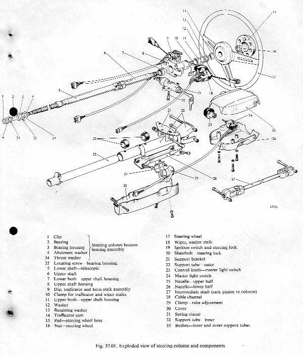
steering-wheel, steering-column, and related components are shown in Fig.
57.0 1. The steering column comprises an upper shaft and a lower shaft,
connected by a needle-bearing universal joint.
The upper shaft is supported by a housing to which the light, trafficator,
wiper stalks, and steering lock controls are fitted.
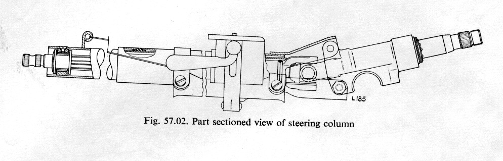
The lower shaft is telescopic and is enclosed and supported by a
two-piece tubular housing. In the
event of impact, due to collision, both the lower shaft and its housing will
collapse and prevent the steering-wheel being thrust towards the driver. (Fig.
57.02.)
An
intermediate shaft connecting the rack pinion and the steering-column lower
shaft is fitted with two splined universal joints. All universal joints are lubricated on assembly and require
no attention in service.
Steering-column
adjustment for both axial movement (4 in., 102 mm.) and rake (2 in., 51 mm.), is
provided by a single clamp lever located in front of the nacelle.
The
16 in. (407 mm.) three-spoke steering-wheel incorporates a padded rim and boss.
Four turns are required from lock to lock.
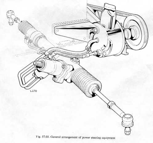
Power
steering equipment shown in Fig. 57.03 comprises
an hydraulic pump, a combined steering rack and ram chamber, and a control valve
and pinion assembly.
The
function of the power steering equipment is to minimize the physical effort of
turning the steering-wheel, especially when parking or maneuvering in restricted
space. The input torque to operate
the steering unit is IO lb. in. (0- 1 15
kg m.) per degree.
When
the engine is not running, or if for any reason the hydraulic system is
inoperative, the vehicle can be steered by direct mechanical effort.
The
engine-driven hydraulic pump supplies pressurized oil to a rotary-type spool
valve which forms an extension of the rack pinion shaft.
Movement, imparted to the rotary valve from the steering column is via a
torsion bar, the deflection of which determines the relationship of the spool
ports and thus the hydraulic power to be directed to one or other side of the
steering-rack piston.
Initial
power assistance is obtained at approximately " deflection of the torsion
bar. Maximum assistance is obtained
at approximately 4' deflection of the torsion bar. When the torsion bar is deflected to approximately 7', direct
mechanical drive is obtained.
Description
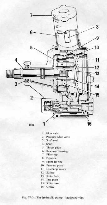
A
combined hydraulic pump and fluid reservoir unit, shown sectioned in Fig.
57.04, is secured to the engine by two brackets and belt-driven from the
engine crankshaft pulley. Two
flexible hoses one delivery, one return-connect it to a control valve on the
steering-rack.
A
rotor with 10 floating vanes is fitted to the pump shaft and is enclosed by an
elliptical ring which provides two diametrically opposed pumping chambers.
Fitted front and rear of the rotor are, respectively, a thrust plate and
a pressure plate. These plates employ dowel pins to align them with the
elliptical ring and pump body. A
tapered compression spring, assisted by pump output pressure, maintains
controlled loading of the pressure plate. An
end-plate located by a circlip and sealed by an 'O' ring provides a division
between pump and reservoir.
Below
the rotor, from which it is supplied, is a combined flow valve/relief valve, and
the pump delivery union. Oil,
returned from the rack control valve, is fed directly to the reservoir.
Operation
Oil,
from the reservoir, is admitted via a drilling in the pump body to the underside
of the pump rotor, from whence, through portings between the rotor and thrust
plate and also the rotor and pressure plate, it is admitted to the pumping
chambers. From the pumping chambers
the oil is expelled to the discharge chamber, and, via a drilling in the pump
body, to the pump outlet union. Pressurized
oil in the discharge chamber is also admitted to the vane roots, thus ensuring
that the vane tips follow the contours of the elliptical ring.
At
the pump outlet union the oil passes via a slot on the piston crown of the
flow/relief valve and is delivered to the rack control valve.
As
its name suggests the flow/relief valve serves a dual function, namely to
provide escape for pressurized oil when steering demands require limitation (for
example, when the road wheels are on full lock and excessive pressure would
overload the rack seals), and also to ensure that oil flow is adequate to
pressurize the rack chamber as required.
Briefly,
the flow/relief valve comprises a piston, the crown of which is exposed to pump
pressure, the other end bears against a compression spring.
Within the piston is a spring-loaded ball-type relief valve.
Fig. 57.04 shows the flow/relief valve and
its associated ports. The need for high rack chamber pressure is greatest when maneuvering
or parking and usually coincides with reduced pump speeds and high frictional
resistance between tyre and road due to zero or low rolling speed.
The flow/relief valve therefore has to cater for a range of flow and
pressure variations ranging from high volume flow and no steering demands
(vehicle traveling in straight line at high speed), and low volume flow and
maximum steering demands (vehicle stationary, engine idling, full lock).
From
Fig. 57.04 it will be evident that pump discharge pressure, acting on the piston
of the flow valve, will tend to displace the piston against the action of its
compression spring, thereby increasing oil flow through the outlet union, to the
rack control valve, or, when the piston is displaced sufficiently, to uncover
the escape port, allowing oil to return to the reservoir.
This latter position is the normal working position of the piston, as
discharge from the pump is always in excess of power steering requirements and
oil is constantly being circulated externally.
However, oil admitted to the outlet union also has access, via an orifice
and transfer passage, to the spring chamber of the flow piston where it is
further assisted by the spring.
Since
piston area, front and rear, are equal, given hydraulic balance the spring will
oppose pump pressure and tend to restrict piston displacement, but since
movement of the piston towards the outlet union must create restriction in oil
flow and a consequent pressure increase, the piston adjusts bleed off or escape
to the reservoir to match the pressure and flow requirements of the rack control
valve. Influence on piston
displacement is also applied by the orifice in the transfer passage to the
spring chamber as its presence introduces a delay factor in pressure adjustment
between spring chamber and piston crown. The
interaction of these forces causes the flow piston to be hydraulically
self-compensating to match pump pressure with steering power requirements, and
by means of the relief valve to impose Imitation on pressure increases within
750 to 850 p.s.i. (52-73 to 59-76 kg./cm.2).
Maintaining
the hydraulic pump
Attention
to the hydraulic pump in service requires only that the fluid level is
maintained at the high mark on the reservoir dipstick, and that the drive belt
is not damaged or unduly worn, and is adequately tensioned.
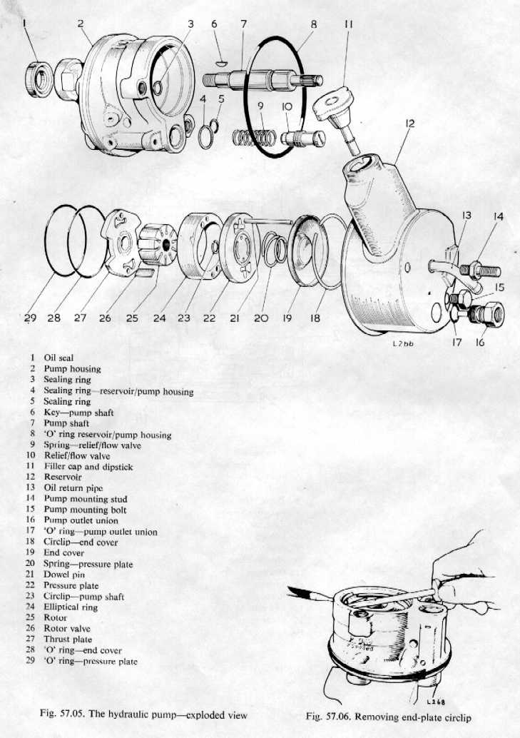
Dismantling
the hydraulic pump (Refer
Fig. 57.05)
Where
'front' and 'rear' are mentioned, interpret 'front' to indicate pulley end of
pump.
Drain oil from reservoir and clean exterior of pump.
Remove
nut and washer securing pulley to shaft.
Using
a suitable puller withdraw pulley. Do
not attempt to hammer shaft from pulley, or lever
pulley from shaft as this may
cause internal damage to pump.
Withdraw
Woodruff key from pump shaft.
Remove
mounting bolts and studs from front and rear of pump body.
Remove
pressure outlet complete with 'O'ring and withdraw relief valve/flow valve
and spring.
Separate
reservoir from pump body.
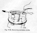
Remove
circlip securing end-plate. To
facilitate the removal of this circlip a small hole is drilled in
the body casing to permit the insertion of a pin punch or
stiff wire (Fig. 57.06).
Withdraw
end-plate and spring, and extract end-plate 'O' ring from pump body.
Carefully
slide pump shaft to rear of body and withdraw shaft complete with pressure
plate, thrust plate, and rotor assembly.
Remove
thrust plate, dowel pins, eccentric ring, and rotor vanes, and examine all
components.
The
thrust plate and rotor hub may be separated from the pump shaft by removing
the circlip from the
shaft.
Assembling
the hydraulic pump (Refer
Fig. 57.05)
Where
'front' and 'rear' are mentioned, interpret 'front' to be pulley end of pump.
Ensure
all components are thoroughly clean. The
shaft oil seal, and all 'O' rings, should be renewed on assembly.
If
the thrust plate and rotor hub have been disturbed, fit them to shaft and
secure with new circlip. Ensure
ported face of thrust plate is adjacent to rotor hub.
Lubricate
shaft bush and lips of oil seal and carefully enter shaft in pump body.
Align
pressure plate dowel holes with pump body and insert the two dowel pins.
Locate
eccentric ring on dowel pins, making sure rotation arrow is to rear of pump.
Fit
vanes to rotor hub slots (curved edges of vanes towards eccentric ring).
Using
hydraulic fluid, lubricate eccentric ring, vanes, and rotor hub.
Install pressure plate 'O' ring in pump body and smear with
hydraulic fluid.
Enter pressure plate evenly in body (ported face towards rotor
hub) and engage dowel pins. Press
gently into position (hand only).
Fit
end plate 'O' ring to pump body.
Locate
tapered coil spring in pump body, engaging larger diameter coil in recessed
seat in pressure plate.
Smear
perimeter of end plate with hydraulic fluid and evenly insert end plate into
pump body until it is slightly below groove of retaining circlip.
Fit
circlip to pump body and release end plate.
Fit reservoir 'O' ring to pump body.
Fit rubber seals into recesses in rear face of pump body.
Carefully
and evenly slide reservoir over pump body, ensuring that mounting holes are
aligned and mounting bolt sealing rings are not dislodged.
Fit
reservoir mounting bolts and studs.
Insert relief valve spring, relief valve/flow valve.
Fit
new 'O' ring to outlet union and screw union into position.
Install key in drive shaft and fit pulley and securing nut.
The
power steering rack and control valve (Refer
Fig. 57.03)
The
power steering rack is similar to normal rack-type mechanisms except that the
rack shaft is fitted with a single piston which operates in an enclosed sealed
chamber. By means of the spool-type
control valve/pinion assembly, pressurized oil from the engine-driven hydraulic
pump is directed to one or other side of the rack piston, thus providing power
assistance to deflect the front road wheels as required.
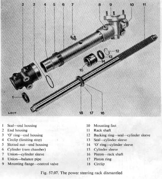
Dismantling
power steering rack (Refer
Fig. 57.07)
Remove
rack complete from vehicle.
Slacken
clips securing bellows seals and slide bellows seals along tie-rods to
expose inner ends of tie-rods.
Wipe
inner ends clear of grease and straighten tab ends of innermost lock
washers.
Unscrew
tie-rods from rack. Care must
be taken not to disturb adjustment of the inner ball joint.
Disconnect
unions connecting rack pipes to control valve and rack chamber, and remove
pipes.
Slacken
locknut on rack plunger adjusting screw and withdraw adjusting screw,
spring, and plunger.
Remove
the three Nyloc nuts and washers securing control valve flange to rack and
withdraw control valve and gasket.
Withdraw
seal housing and washer from rack.
Disconnect
unions securing rack balance pipe and remove balance pipe.
Using
a suitable 'C' spanner, release screw securing end-housing to rack cylinder
and withdraw end-housing,
Remove
union from centre of rack clinder.
Withdraw
rack shaft complete with piston in direction of end-housing.
NOTE:
This operation invariably results in the rack teeth being drawn through
the lip-type seal in the cylinder sleeve. It
is essential that this seal is renewed when the rack shaft is removed.
It is recommended that all seals
are renewed once they have been disturbed.
14.
Remove circlips and extract piston from rack shaft.
Take care that circlips do not score rack shaft.
Assembling
power steering rack (Refer
Fig. 57.07
Thoroughly
clean all components.
Fit
new seal and nylon backing ring to cylinder sleeve.
Note that seal lip must be fitted adjacent to tapped locating hole
and that square edge of nylon ring must abut against seal.
Fit
new 'O' rings to cylinder sleeve and lubricate cylinder bore with hydraulic
oil.
Lubricate
seal lip and enter cylinder sleeve (seal leading) over rack shaft at
opposite end to rack teeth.
Fit
piston inner 'O' ring to rack shaft.
Carefully
slide cylinder sleeve (seal end first) along plain end of rack shaft beyond
location of piston. Do
not slide cylinder sleeve over rack teeth.
Fit
piston inner circlip to rack shaft, taking care not to mark or score rack
shaft.
Fit
piston ring to piston, slide piston into position on rack shaft and secure
with circlip, taking care not to score or mark shaft.
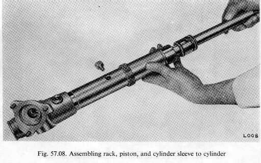
Align tapped hole in cylinder sleeve with countersunk hole in
cylinder and carefully slide sleeve and rack shaft into cylinder (Fig.
57.08).
Through
countersunk hole in cylinder, locate tapped hole in cylinder sleeve.
Ensure
end-cover securing ring towards open end of cylinder, smear conical seat of
union with hydraulic sealing compound and fit and tighten union securing
cylinder sleeve.
Fit
new lip-type seal (lip of seal towards cylinder bore) and 'O' ring to end
cover.
Lubricate seal lip and slide end cover into position
Line
up mounting feet and secure end cover by tightening screwed retaining ring.
Fit
lip seal and 'O' ring to retainer. Fit washer into recess in pinion housing and fit ring (lip
seal downwards). (Fig. 57.09.)
Fit
new gasket to control valve flange.
Locate
rack shaft in cylinder so that rack teeth are visible through control valve
flange and are aligned to permit engagement of pinion.
Carefully
enter pinion through seal and engage rack teeth, locating control valve over
studs. Fit and tighten the three Nyloc nuts.
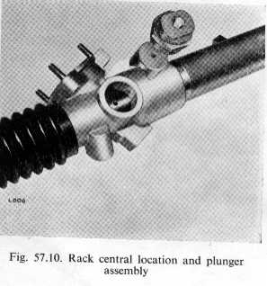
Rotate
pinion until rack is centralized, i.e. the dimple on rack shaft lies in the
middle of the thi-ust plunger aperture. (Fig.
57.10.)
Remove
the small hexagonal plug from the screwed plug and using a dial gauge
tighten screwed plug until plunger end-float (i.e. side movement of the rack
shaft) does not exceed 0.007 in.
(0.178
mm.). This measurement must not be confused with backlash or axial movement. Tighten locknut.
Fit
grease nipple to screwed plug and grease rack.
Remove
grease nipple and replace hexagonal plug.
Fit
new end washers complete with 'D' plates to rack ends (recessed side of
washer towards rack).
Fit
and tighten tie-rod inner ends to correct torque figure.
Both tie-rod inner ends should be tightened simultaneously to prevent
stress to pinion. Secure by
bending over lock tabs on 'D' plates, care being taken not to disturb ball
housing tabs. Ball joints to be
checked for free articulation following assembly to rack.
Grease
rack ends and inner ball ends, slide bellows seals into position, and secure
with clips.
Fit
Bundy tubing to control valve and rack housing.
If
necessary, during assembly of rack, the pinion lower needle bearing and rack
shaft bush in end housing can be renewed.
Description
and operation
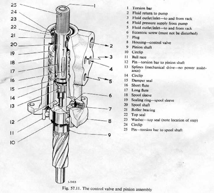
The
steering rack control valve is a combined pinion shaft and spool valve assembly
through which oil flow from the hydraulic pump is directed to either side of the
rack piston as required. A cutaway
view of the control valve is shown in Fig. 57.11 together
with a sectioned plan view (Fig.57.12). From
these illustrations the construction and principle of operation can be seen.
The
ports in the control valve body are connected, in order of descent, as follows:
Top-return
to reservoir.
1st intermediate-delivery to, or return from one side of rack piston.
2nd
intermediate-pressure supply from pump.
Bottom-delivery
to or return from other side of rack piston.
Forming
the spool valve is a shaft with six flutes, three long and three short,
alternately disposed. This shaft is
encased by a sleeve which has six internal axial channels, and on its external
surface, three circumferential grooves interspaced with sealing rings.
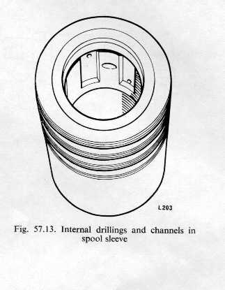
The centre circumferential groove has three drillings at 120' which
penetrate the plain area of the internal bore.
The top and bottom circumferential grooves also are drilled, but these
holes (three at 120' each groove) are smaller than
those of their centre counterpart and penetrate the top and bottom
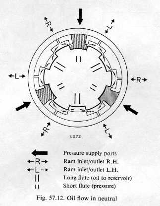
respectively of the internal axial channels as shown in Fig.
57.13. When assembled, the shaft and sleeve are as shown in Fig. 57.12,
i.e. with the centre circumferential groove drillings aligned with the short
flute and the smaller drillings in the top and bottom grooves aligned with the
plain (unfluted) surface of the shaft. As illustrated (Fig. 57.12) this
is neutral or straight-ahead position, a position which requires no steering
assistance. This delicate
relationship of sleeve and shaft is the responsibility of the eccentric screw
shown in Fig.57.11. No
adjustment must be made to the eccentric screw in service.
So
long as the hydraulic pump is running, oil is delivered under pressure to the
central circumferential groove of the sleeve, and, via its three drillings, to
the short flutes machined in the shaft.
A
feature of the shaft flutes is the carefully ground tapered chamfers at the
flute sides. These chamfers allow
oil to flow, in neutral, to adjacent sleeve channels and also to the long
flutes, where, with escape unrestricted, the oil can pass above the sleeve and
return to the pump reservoir. The
flute chamfers, however, serve the system in other ways: their presence prevents
abrupt changes in pressure differentials, and also, because of the
characteristics of oil flow, together with the torsion bar, provides the
retention of driver 'feel'.
When
the steering-wheel is turned to right or to left the deflection of the torsion
bar to which the control valve shaft is pinned allows the shaft to move
initially independent of the sleeve, thus altering the relationship of the shaft
flutes to the internal axial channels of the sleeve.
The result is that oil is now supplied to three of the sleeve internal
channels only and is passed to either the top (left-hand turn) of the sleeve
circumferential groove from whence it is fed to the appropriate side of the rack
piston. Since pressure on one side
of the rack piston necessitates oil displacement on the other side, the
displaced oil from the unpressurized side of the rack piston is returned to the
sleeve circumferential groove which is not pressurized and escapes to the
reservoir via the long flutes.
When
the torsion bar is no longer subjected to deflection, i.e. when effort has
ceased to be applied to the steering-wheel rim, the shaft flutes are restored to
their neutral position (Fig. 57.12) and pressure
differences within the ram chamber cancelled.
Attention
to the control valve is not recommended as its construction and setting does not
favour dismantling. Where, however,
the top oil seal requires renewal, this operation may be carried out provided
care and scrupulous cleanliness are observed. It is necessary to emphasize that the eccentric screw locating
the spool sleeve MUST NOT be disturbed.
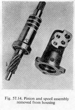
Removing
and replacing control valve top seal (Refer
Figs' 57.11 and 57.14)
Thoroughly
clean exterior of control valve end unions.
Disconnect
flexible hoses and steel pipes at control valve and seal all apertures to
prevent ingress of grit.
Release
plunger load from rack shaft.
Remove
the three Nyloc nuts from control valve flange and withdraw control valve.
Carefully
press pinion shaft and extract pinion and shaft from underside of control
valve. Note that pressure must
not be applied to the pinion shaft torsion bar.
The
withdrawal of the pinion shaft will expose the spool valve which is fitted
with special sealing rings and is located by an eccentric screw (Fig.
57.14). Neither the special rings nor the eccentric screw are to be
disturbed in any way. Disregard
of this instruction may result in a requirement for a new control valve.
Remove
circlip, backing washer and seal from control valve body; renew seal and
replace in reverse order.
Using
special sleeve (Tool No. J-34), insert pinion shaft and spool valve into
body.
Remove
special sleeve (Tool No. J-34) from pinion shaft.
Refit
control valve to rack, ensuring pinion teeth do not damage lip of control
valve lower seal.
Adjust
and lock rack plunger.
Removing
and replacing control valve seat inserts
Seat
inserts are fitted to the inlet and return ports of the control valve housing. These seats can be damaged due to over tightening of the
flexible hose unions.
Seat
removal can be accomplished by using an 'Easy-Out' extractor.
Carefully fit a new insert, observing scrupulous cleanliness as the
admission of swarf or grit may render the control valve inoperative.
IMPORTANT:
The insert in the control valve pressure inlet port is also a restrictor.
This insert, or restrictor must be chosen to suit the hydraulic pump
fitted.
The
hydraulic steering system is self-bleeding, but care must be taken to ensure
that at no time is the pump reservoir allowed to empty or become dangerously
low. This is especially important where both the pump and the rack
have been newly installed.
When
the hydraulic system has been disturbed, proceed as follows.
Ensure
all hydraulic connections are properly made and tight.
Fill
hydraulic reservoir to high level mark on dipstick.
Place
road wheels in straight-ahead position, and with drive belt slackened or
removed rotate pump pulley by hand to prime system.
Fit
and adjust drive belt.
Check,
and top up hydraulic reservoir as necessary.
Start
engine and allow to idle.
Turn
driving wheel to full lock and return wheel to straight-ahead position.
Check
and top up reservoir.
Turn
driving wheel to opposite lock and return to straight-ahead position.
Again
check reservoir level.
Turn
wheels from lock to lock several times to permit air to be fully exhausted
from system.
Return
wheel to straight-ahead position and give final check to reservoir level.
NOTE:
While repeated turning of the steering-wheel when the car is stationary
will do the steering mechanism and hydraulic units no harm, the effect on tyre
treads is not so favourable. When testing or bleeding the power steering, the road wheels
should be rotating slowly to minimize tyre scrub.
Should
steering defects arise in service, careful analysis is advised before
attributing blame to the power steering equipment and embarking on the
dismantling of hydraulic units. Heavy
steering and pull to one side may be caused by mechanical faults; wheel track,
tyre treads, tyre pressures, wheel bearings, steering geometry, and wear and
stiffness in linkage must first be checked.
Where
examination eliminates mechanical faults, the testing of the hydraulic system is
explained
below.
1.
Check reservoir level and carefully examine steering units and hoses for
leaks. All leaks must be rectified
before attempting to test system.
2. Check pump drive belt for condition and
tension.
3. Release rubber bellows seals from
rack-ends and examine for fluid leakage.
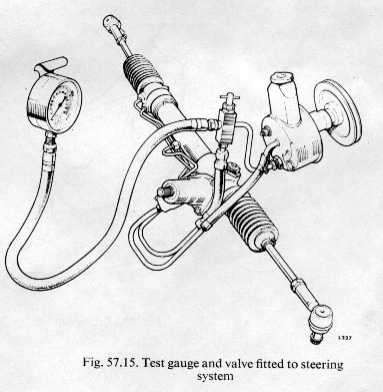
4. Fit test gauge (JD10 and adaptor 10-2)
to pump delivery (outlet) line as shown in Fig. 57.15.
5. Ensure all air is exhausted from the
circuit, the oil level in the reservoir is correct, and that the oil is at
working temperature.
6. With test-cock open and engine running,
gently turn steering-wheel to left and right lock whilst observing gauge.
A pressure of 750 to 859 p.s.i. (52.73 to 59.76 kg/cm2) should be
recorded in both cases. If pressure
within this range is not obtained, or marked pressure imbalance is recorded, a
fault exists in the system.
7. To determine if the fault is in the
rack circuit or in the pump, close the test-cock for a period not
exceeding five seconds. If the
gauge fails to register 750 to 850 p.s.i. (52.73 to 59.76 kg/cm.2), the pump is
inefficient and the pump relief valve/flow valve should be examined/renewed as
necessary.
8. Repeat above test after renewing relief
valve/flow valve and bleeding system. If
the pump still fails to deliver oil at 750 to 850 p.s.i. (52.73 to 59.76 kg./cm .2)
, attention to the pump, or a new exchange unit is required.
9. If pump delivery is satisfactory and
low pressure or marked imbalance exists, the fault must be in the rack control
valve, or be caused by internal leakage in the rack cylinder.
10. Remove rack cylinder pipe unions from rack control
valve body. Using suitable plugs,
seal rack cylinder ports in control valve body.
11. With engine idling, turn steering-wheel gently to
left and right, observing gauge reading. Do
not hold wheel in either direction
for periods exceeding five seconds. Check
that pressures of 750 to 850 p.s.i. (52.73 to 59.76 kg./cm.2) are obtained in
both directions.
NOTE: Since fluid is now being supplied to the rack the
steering will naturally be heavier. It
is quite unnecessary, however, to attempt to impart movement to the road wheels
since the object of this test is merely to record pressure obtained at maximum
torsion bar deflection.
12. If the control valve is found satisfactory, the fault must be within the rack.
| FAULT | Cause | Remedy |
|
Heavy steering |
|
|
| Steering pulls to one side |
|
|
|
Backlash in steering-wheel couplied with insensitive handling |
|
|
| Jerky or inconsistent response when turning |
|
|
SERVICING
POWER STEERING COMPONENTS IN SITU
Adjusting
hydraulic pump drive belt
Renewing
hydraulic pump drive belt
Remove
and replace relief/How valve
Raise
car on ramp or jack.
Clean area in vicinity of flexible pipe unions on hydraulic pump.
Disconnect
outlet union at pump. This will
result in spillage of hydraulic fluid and a container should be available
for this purpose.
Remove
pump outlet union.
Withdraw
relief/flow valve and spring.
Replace
in reverse order, noting that filter end of valve is fitted adjacent to
spring.
The
outlet union 'O' ring should be renewed.
Top
up reservoir, bleed system and check for leaks.
Removing
and replacing flexible hoses (Refer
Fig. 57.03)
Thoroughly
clean areas in vicinity of flexible hose unions at control valve and
hydraulic pump.
Disconnect
unions at control valve and pump. (The oil return hose is fitted with a
union at control valve end and a clip at pump end.)
Replace
in reverse order.
Top
up reservoir, bleed system and check for leaks.
Flexible
hoses must be renewed if signs of chafing, softness, or perishing become
evident. Do not use substitute
hoses.
Removing
and replacing hydraulic pump
Disconnect
oil delivery and return pipes at hydraulic pump.
Remove
nut and washers securing pump to rear bracket.
Slacken
the two bolts securing pump to front bracket, pivot pump towards engine, and
release drive belt from pump pulley.
Remove
the two bolts securing pump to front bracket.
Remove
nuts and washers securing rear bracket to engine cylinder block.
Withdraw pump and rear bracket.
Replace
in reverse order.
Adjust belt tension, top up reservoir and bleed steering system.
Renewing tie-rod outer end
Remove
road wheel.
Scribe
a line on one flat of the tie-rod outer end locknut and a corresponding line
on tie-rod. Slacken locknut.
Release
tie-rod from steering-arm and unscrew tie-rod outer end.
Screw
on new outer end, ensuring it will be located in the same position on the
tie-rod as the old one. That
is, that the length between ball centres is not altered.
Connect
and tighten tie-rod end to steering-arm.
Repeat
above procedure on opposite side.
Fit
road wheels and check track, adjusting as necessary.
Wear
in tie-rod outer ends cannot be removed by adjustment; renewal of the complete
end is necessary. Tie-rod outer
ends should be renewed in pairs.
Renewing
bellows seal
Remove
front wheel.
Remove
tie-rod outer end and locknut.
Clean
area around bellows.
Release
clips securing bellows seal to rack housing and tie-rod and slide off
bellows seal.
Ensure
tie-rod inner end is adequately greased, pack new bellows seal with
approximately 2 oz. of grease and slide into position.
Secure
inner end of seal to rack with a clip or twist of wire, taking care not to
cut or bite into seal.
Position
outer end of bellows seal 5.75 in. (146 mm.) from outer end of tie-rod and
secure with clip.
Replace
locknut and tie-rod outer end and secure to steering-arm.
Fit
front wheel, lower vehicle to ground and check and adjust wheel track as
necessary.
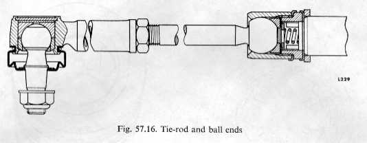
Renewing
tie-rod (Fig.
57.16)
Remove
front wheel, disconnect tie-rod outer end from steering-arm and withdraw
outer end and bellows seal.
Turn
steering-wheel as necessary to expose tie-rod inner end.
Straighten
lock tabs securing ball end to rack on inner lock washer.
Unscrew
tie-rod.
Replace
in reverse order, ensuring inner lock tabs are renewed and properly secured.
Both tierod inner ends must be tightened simultaneously to prevent
stress being applied to pinion teeth.
Check
tie-rod inner ball joints for free articulation.
Check
and adjust wheel track as necessary.
Tie-rod
inner end (Fig.
57.16)
Wear
in tie-rod inner ends can be adjusted by shim removal provided the ball end is
not stepped and ovality is not present in ball seats.
Properly
adjusted, and with tab washer securely locked, the tie-rod should pivot evenly
about its seat. Stiffness in
tie-rod articulation, whether throughout its movement or in spots, rhust not be
tolerated.
End-float
should be within 0.0005 to 0.003 in. (0.0127 to 0.0762 mm.).
The
torque setting of ball housing to adaptor is 80 to 90 lb. ft.
This is critical.
If
ball joints are secured to rack at a higher torque it could result in the tab
washer being disturbed and also overtightening of the ball joints.
Tie-rod
length
Tie-rod
lengths should be set initially to 9-74 in. (247-396 mm.) between ball centres.
Subsequent adjustment made to obtain correct track setting should be made
equally to both rods.
Removing
and replacing rack control valve
Should
removal of the rack control valve be required, it is advised that the rack be
removed from the vehicle. This
recommendation is made principally to minimize the entry of grit to either rack
or control valve and also to eliminate damage to the control valve lower seal if
the pinion is inserted in situ.
NOTE: Before refitting control valve to rack it is advised that the rack
thrust button is first released of load.
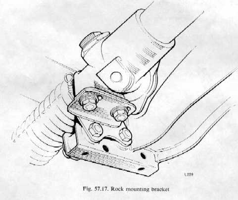
Removing
rack (Fig.
57.17)
1. Raise car on ramp or jack.
2. Remove pinch-bolt and nut from pinion shaft universal
joint.
3. Clean control valve in vicinity of pipe unions.
4. Disconnect, at control valve housing, the main oil supply
and return unions (flexible pipes).
5. Plug, or seal off, disconnected unions and control valve
ports to prevent entry of grit.
6. Disconnect tie-rod ends from steering-arms.
7. Remove the four bolts, plain and spring washers, and angle plates
securing rack mounting feet to mounting brackets.
8. Withdraw rack forward to release pinion shaft from universal
joint and remove from car.
Replacing
rack
1
. Centralize rack and
position it on car.
2. With front road wheels and steering-wheel set in straight-ahead
position, engage pinion shaft in steering shaft universal joint ensuring that
the flat machined in pinion shaft corresponds with bolt location in universal
joint.
3. Align tapped holes in rack feet with those in mounting brackets and
engage single plates, bolts, plain and spring washers.
Ensure single plates are in contact with mounting platform before
tightening bolts.
4. Connect tie-rod ends to steering-arms.
5. Fit pinch-bolt to universal joint and pinion shaft.
6. Connect flexible pipe unions to control valve.
7. Top up hydraulic reservoir, bleed steering system and
check for leaks.
8. Check also that the rack Bundy pipes do not make contact either with
each other or any part of the car.
Hydraulic
pump
Fluid
capacity (including reservoir). .
1.75 Imp. pts. (0.995 litres) approx.
Pump
delivery: Min...
1.04 Imp. g.p.m. (4.727 litres) at 170' F. at
465 r.p.m. against 665 to 735 p.s.i. (46.75 to
51.67 kg. /CM.2)
Max.
1.79 Imp. g.p.m. (8.138 litres) at 170' F. at
1,500 r.p.m. against 50 p.s.i. (3-515 kg./cm.')
Relief valve
750 p.s.i. (52.73 kg./cm .2) min., not exceeding
850 p.s.i. (59.76 kg./cm .2
) at 1,500 r.p.m.
TORQUE FIGURES
Hydraulic
pump
Pump reservoir to housing
35 lb. ft. (4-85 kg. in.)
Pump to mounting bracket 34 lb. ft. (4-84 kg.
in.)
Pressure
hose unions . .
25 lb. ft. (3-46 kg. m.)
Relief
valve union
25 to 40 lb. ft. (3-46 to 5-53 kg.m.)
Control
valve
Flange
nuts
10 to 14 lb. ft. (1.38 to 1.94 kg. m.)
Unions-Bundy tubing
12 to 16 lb. ft. (1 .66 to 2.21 kg.m.)
Rack
Locknut-rack
plunger
55 to 65 lb. ft. (7.6 to 8.99 kg.m.)
Slotted
nut-cylinders and housing. .
80 to 90 lb. ft. (11.06 to 12.44 kg. m.)
Inner
ball joint to adaptor
80 to 90 lb. ft. (11.06 to 12.44 kg.m.)
Adaptor-cylinder
sleeve
25 to 29 lb. ft. (3.46 to 4.02 kg. m.)
Unions-Bundy
tubing
12 to 16 lb. ft. (1.66 to 2.21 kg. m.)
Tie-rod-inner
end
40 to 50 lb. ft. (5.53 to 6.92 kg. in.)